

Performance Comparison: SiC MOSFET vs Si IGBT
The benefits of the SiC material are described earlier. Let’s now explore how SiC MOSFETs stack against the Si IGBTs in terms of performance metrics from the designers and engineers’ perspective. The performance metrics we consider are conduction losses, thermal performance, switching speed & switching losses, gate driving requirements and control considerations.
Conduction Characteristics (On-State Losses)
As explained in our detailed blog MOSFET vs IGBT, the IGBT behaves like a diode in the on-state, with a small voltage drop plus a small resistive load. This VCE(sal) is 1-2 V for the rated current of many IGBTs. Until the device’s limit is almost reached, this voltage drop does not increase. A MOSFET, on the other hand, acts as a resistor. At a smaller current, it drops lower voltage. However, MOSFET linearly increases the voltage drop predictably using formulae IRDS(on) as the current increases. Engineers favored IGBTs over MOSFETs because, at higher currents, IGBTs maintained a lower voltage drop than MOSFETs operating under the same conditions.
When comparing SiC MOSFET vs Si IGBT, we discovered that SiC MSOFETs change this scenario drastically. SiC MSOFET can have lower RDS(on) despite higher voltages ranging from 1200 V to 1700 V. For example, a state-of-the-art SiC MOSFET may have only 25 mΩ on-resistance at 1200 V. This astounding feat means this SiC MOSFET can pass 50A current and still drop only around 1.25 V – a comparable number to the IGBT performance.
SiC MOSFET vs Si IGBT: Thermal Performance
The lower RDS(on) also has an effect on the thermal performance of the power transistor device, whether MOSFET or IGBT. At let’s say 150 °C, the VCE(sal) of IGBT, and RDS(on) of the MOSFET rise.
In examining the SiC MOSFET vs Si IGBT, due to the better thermal performance of SiC material, the SiC MOSFETs offer outstanding low on-resistance, closing the gap in high-current use cases while retaining the low-drop advantage at higher current applications.
Switching Speed and Switching Losses
As indicated earlier, IGBTs suffer from tail current, limiting their ability to swiftly turn on or off. This is exactly where the MOSFETs in general and SiC MOSFETs in particular truly shine. A MOSFET responds almost immediately to the gate voltage compared to an IGBT’s slow turn-on and off times. Practically, SiC MOSFETs complete switching transitions in tens of nanoseconds, while IGBTs take hundreds of nanoseconds or even microseconds at similar voltage levels.
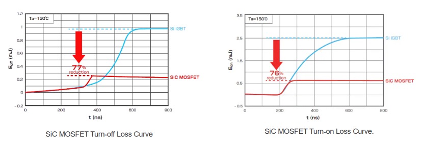
Due to fast switching speed, the SiC MOSFET has lower switching loss (Eon) and Eoff)compared to an IGBT of equal rating. In an experiment to validate these statements, Toshiba took a single-phase inverter model functioning with a 1200 V Si IGBT. The same inverter was then tested with a 1200 V, 70 mΩ SiC MOSFET. At 800 V, 10 A switching, each turn-off of the SiC MOSFET had ~78% less energy loss than the IGBT the similarly rated IGBT.
The example of switching-on and switching-off loss reduction is shown in the following curves:
In further investigation, when an Si IGBT in this inverter was replaced with 2nd generation SiC MOSFET, the turn-on and turn-off losses were significantly reduced as demonstrated in the following table
| Device | Switching Loss | |||
| Conduction loss | Turn-on | Turn-off | Total loss | |
| IGBT | 4.4W | 3.1W | 6.9W | 14.4W |
| SiC MOSFET | 4.5W (~ 2% up) | 2.5W (~ 19% down) | 1.5W (~ 78% down) | 8.5W (~ 41% down) |
IGBTs have inherently slower switching, particularly at higher voltages of around 1200V or up, and substantial losses. In contrast, the SiC MOSFET switch is orders of magnitude faster than the Si IGBT. Also, SiC MOSFETs can do this with far less energy losses, yielding higher efficiency at any given frequency.
SiC MOSFET vs Si IGBT Gate Driving Requirements Considerations
At the control level, both Si IGBT and SiC MOSFET are voltage-controlled devices. However, the gate requirements for both devices are different, as demonstrated below:
SiC MOSFET vs Si IGBT: Gate Voltage Level
Traditional IGBTs require ~+15V at the gate to fully turn on. In adverse situations, IGBTs can also handle up to +30 V. Typically, either 0 V or a slight negative voltage (-5V) is used to turn them off. Most SiC MOSFETs, however, require slightly more voltage (+18V) to fully turn them on. SiC MOSFET also benefits from 5V to robustly turn off and avoid false turn-on due to Miller Capacitance.
There is a slight difference between the recommended +18V drive of SiC MOSFET and the device’s max allowable drive voltage (~ +20 V to +22 V), leaving little room for error. So, for SiC MSOFET, precision gate driving is crucial. You might want to protect it using Overvoltage Protection using a TVS diode.
Gate Capacitance and Drive Current
SiC MOSFETs have lower gate charge ( Qg) ) than an IGBT of the same rating. This means that the driving gate at high speed requires less driving power. However, at high frequencies, gate power can add up, with the plus side that the gate drive ICs can handle it optimally.
IGBTs, however, have higher input capacitance and require more gate drive current at a given frequency. Their gate is also intentionally driven more slowly to control di/dt.
SiC MOSFET vs Si IGBT: Gate Driver IC Availability
Due to the potential and interest of the industry in SiC devices, gate driver ICs for both SiC and Si devices are widely available. Especially, the SiC MOSFET gate driver has captured industry’s attention.
Many gate driver chips act as both SiC MOSFET gate driver as well as Si IGBT gate driver. Take the example of the Tamura 2DMB80407CC, which is a dual isolated driver that explicitly supports driving “IGBT or SiC MOSFET” half-bridges.
With the slight inconvenience of adjusting the gate voltage and adding a negative bias supply, driving a SiC MOSFET is not substantially different from driving an IGBT from an engineer’s and designer’s perspective.