

A4988 Stepper Motor Driver IC Features, Pinout & 3D Printer Applications
Introduction
The A4988 stepper motor driver IC is a small DMOS microstepping driver designed for accurate control of bipolar stepper motors. Widely adopted in open-source hardware ecosystems, this component from Allegro MicroSystems takes the digital pulses and converts them to accurate positions in the rotor utilizing internal translator logic, obviating the need to write complex code to sequence the phases of the motor. Basically, the A4988 can supply a little more than 2 A per phase (with proper cooling), and operates from 8 – 35 V, making it a common building block of motion control circuits.
Because of this versatility, Engineers and hobbyists will incorporate the A4988 stepper motor driver into systems where placement needs to be repeatable, such as an automated linear actuator and potentially on a multi axis platform. The driver supplies built-in current regulation and micro-stepping ensure that the mechanical resonance is reduced and operations are smooth, achieving better than 1⁄16 of a full-step resolution. This section will talk about the architecture of the IC, the electrical specifications that apply to the user, and then conclude with details for practical use as a technical introduction to the A4988 driver IC.
What Is the A4988 Stepper Motor Driver?
The A4988 driver is a comprehensive microstepping motor driver with a built-in translator for simple operation. It controls bipolar stepper motors by converting STEP and DIRECTION inputs into sequenced currents in the coils, while maintaining full-step to 1/16-step resolutions, all without the use of external lookup tables. The IC operates from a single supply (8–35 V for motor power, 3–5.5 V for logic), and can deliver up to ±2 A of current per coil (specified as peak) and requires the use of external current-sense resistors.
The microstepping driver regulates sine/cosine current profiles in the motor windings using fixed off-time PWM current regulation. This helps to minimize both torque ripple and audible noise compared to full-step operation. The translator progresses the stepping sequence on each rising edge of the STEP input while the DIR pin determines the direction of rotation. Additionally, the ENABLE pin shuts off all of the outputs to minimize power consumption during idle conditions.
History and Manufacturer Overview
The A4988 Allegro IC was introduced by Allegro MicroSystems in the early 2000s as part of a family of DMOS-based stepper drivers. Allegro, a leader in power ICs, designed the A4988 manufacturer chip to replace discrete transistor bridges in cost-sensitive applications. Its adoption in the RepRap project accelerated widespread use in open-source 3D printing, establishing it as a de facto standard despite newer alternatives.
Basic Working Principle
The working principle is based on using current-mode PWM control. When a STEP pulse occurs, the internal translator increases the reference from the DAC to establish target current levels in each coil. Comparators monitor voltage across the sense resistors that are in series with each coil and once the actual current reaches the DAC level, the bridge will enter decay mode for a fixed off-time (in the directions part of the pulse, this time is normally around 20 µs). This operation proceeds in cycle to track the sine table for microstepping. How the A4988 works: Slow decay during the low-current and fast decay during high-current transitions minimizes ripple. Microstepping explained: The 5-bit DAC divides each full step into 16 equal current increments, for an angular resolution of 1/16-step.
Key Features of the A4988 IC
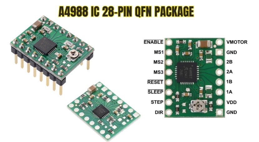
The A4988 is a robust set of integrated protections and control mechanisms in a 28-pin QFN package. Operating voltage spans 8–35 V for motor supply and 3–5.5 V for logic, with continuous output current up to 1 A per phase (2 A peak with heatsinking). In addition, it’s features include automatic current decay mode selection, low RDS(on) DMOS outputs (0.55 Ω typical), and a translator for simplifying microcontroller interface. Microstepping on the A4988 IC supports five resolution settings via MS1–MS3 pins. A4988 current limit is adjustable through an external reference voltage (VREF) and sense resistors.
Microstep Resolutions (Full, Half, 1/4, 1/8, 1/16)
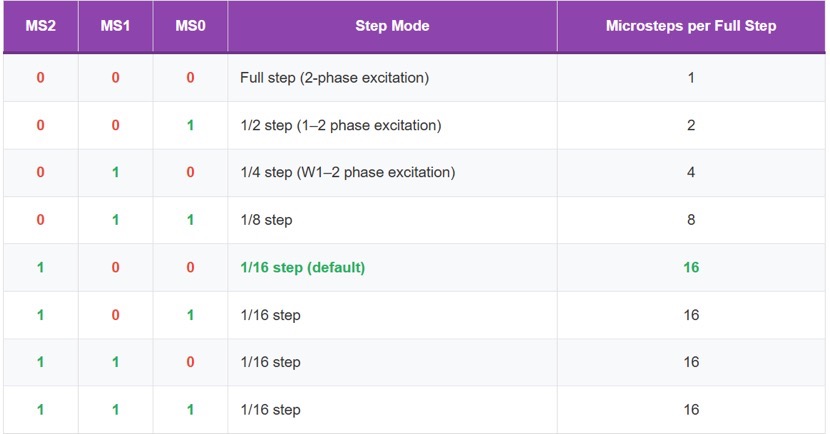
The A4988 microstepping modes are selected by logic levels on MS1, MS2, and MS3 pins, dividing each full step into up to 16 microsteps. The 1/16 step mode provides the smoothest motion, which is achieved by modulating the coil currents in 6.25% increments of full-scale, thereby greatly reducing vibration in low-speed applications. Microstep resolution does not increase absolute positioning accuracy, which is limited by mechanical backlash, but it minimizes resonance and torque variation. The internal sine/cosine lookup table assures proportional current distribution between coils.
A4988 Microstep Resolution Table
Default mode: MS2=1, MS1=0, MS0=0 → 1/16 microstepping (most common in 3D printers).
Overcurrent and Thermal Protection
Built-in A4988 protection circuits disable outputs if coil current exceeds approximately 2.5 A (typical) or if junction temperature surpasses 165 °C. The thermal shutdown feature of the A4988 includes a hysteresis of approximately 15 °C to avoid oscillation during the recovery period. The overcurrent protection circuitry can monitor each MOSFET (high-side and low-side) independently to latch the fault condition until either the ENABLE pin is toggled or power is cycled. These protection features will mitigate catastrophic failures under conditions of short-circuit or stall.
Adjustable Current Chopping
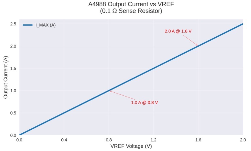
The A4988 current adjustment uses an analog reference voltage (VREF) applied to the REF pin and two external sense resistors (RS1, RS2). Peak current is set by
VREF setting typically ranges 0–2 V; for a 0.1 Ω sense resistor, 1.0 V yields 1.25 A per phase. Current limiting operates via fixed off-time PWM (approximately 20 µs), automatically switching between slow and fast decay to optimize regulation across load conditions.