

A bridge rectifier is an arrangement of four or more diodes in a bridge circuit configuration which provides the same output polarity for either input polarity. It is used for converting an alternating current (AC) input into a direct current (DC) output. A bridge rectifier provides full-wave rectification from a two-wire AC input, therefore resulting in lower weight and cost when compared to a rectifier with a 3-wire input from a transformer with a center-tapped secondary winding.

What is a bridge rectifier circuit?
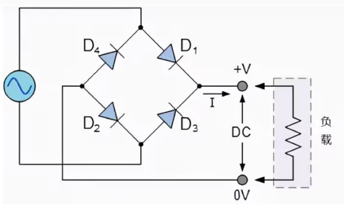
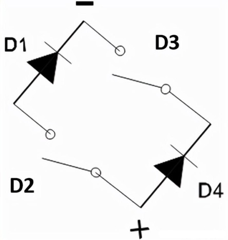
A bridge rectifier circuit is composed of four diodes connected in a closed-loop “bridge” configuration to generate the desired output.
The main advantage of this bridge circuit is that it does not require a special center tap transformer, thereby reducing size and cost. A single secondary winding is connected to one side of the diode bridge network, and the load is connected to the other side, as shown in the following figure.
Working principle of bridge rectifier circuit
During the positive half cycle of the input AC waveform diode, D1 and D2 are forward biased, and D3 and D4 are reverse biased. When the voltage exceeds the threshold level of diodes D1 and D2, conduction begins – the load current begins to flow through it, as shown in the path of the red line in the following figure.
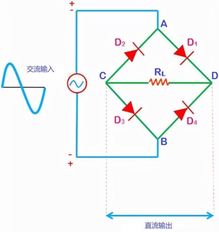
Working principle of positive half cycle of bridge rectifier circuit
During the positive half cycle, diode D3-D2 is forward biased and acts as a closing switch. The diodes D1-D4 are reverse biased and non-conductive, so it’s like opening a switch. Therefore, we obtain a positive half cycle at the output end
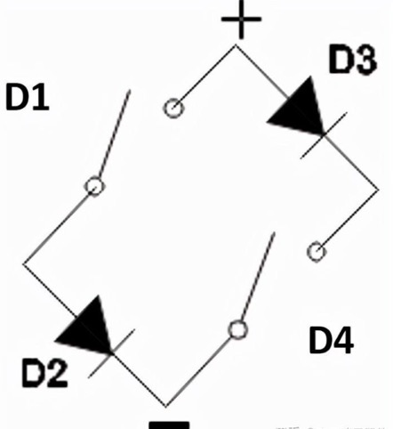

Working principle of negative half cycle of bridge rectifier circuit
During the negative half cycle, diodes D1-D4 are forward biased and function to close the switch. The diode D3-D2 is reverse biased and non-conductive, so it is like opening a switch. Therefore, we obtain a positive half cycle at the output end

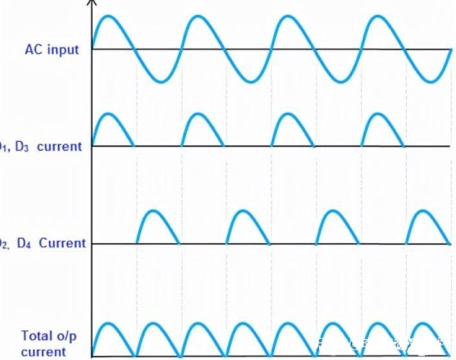
From the above four graphs, it can be seen that during the positive and negative half cycles, the direction of the current flowing through the load resistor RL is the same. Therefore, the polarity of the output DC signal for the positive and negative half cycles is the same. The polarity of the output DC signal can be either completely positive or negative. If the direction of the diode is reversed, we will obtain a complete negative DC voltage.
Therefore, the bridge rectifier circuit allows current during both the positive and negative half cycles of the input AC signal.
The output waveform of the bridge rectifier circuit is shown in the following figure. We can see that the negative part of the AC voltage is converted into a positive cycle after passing through the bridge rectifier circuit.
Characteristic parameters of bridge rectifier circuits
The main parameters of the bridge rectifier circuit include the following
Ripple factor
PIV
Efficiency
Classification of bridge rectifier circuits
Bridge rectifier circuits can be classified into several types based on these factors: power supply type, control capability, bridge circuit configuration, etc. Bridge rectifier circuits are mainly divided into single-phase and three-phase rectifier circuits. These two types are further divided into non controlled, semi controlled, and fully controlled rectifier circuits.
Design considerations for bridge rectifier circuit
Voltage drop
Calculate the heat emitted from the rectifier
Peak Reverse Voltage
Advantages of bridge rectifier circuit:
Low ripple in output DC signal
High rectification efficiency
low-power consumption
Disadvantages of bridge rectifier
The bridge rectifier circuit looks very complex
Compared with the center tap full wave rectification circuit, the power loss is greater
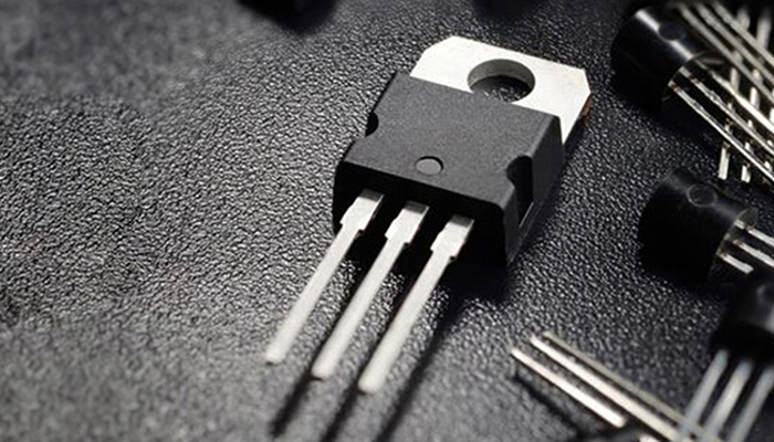
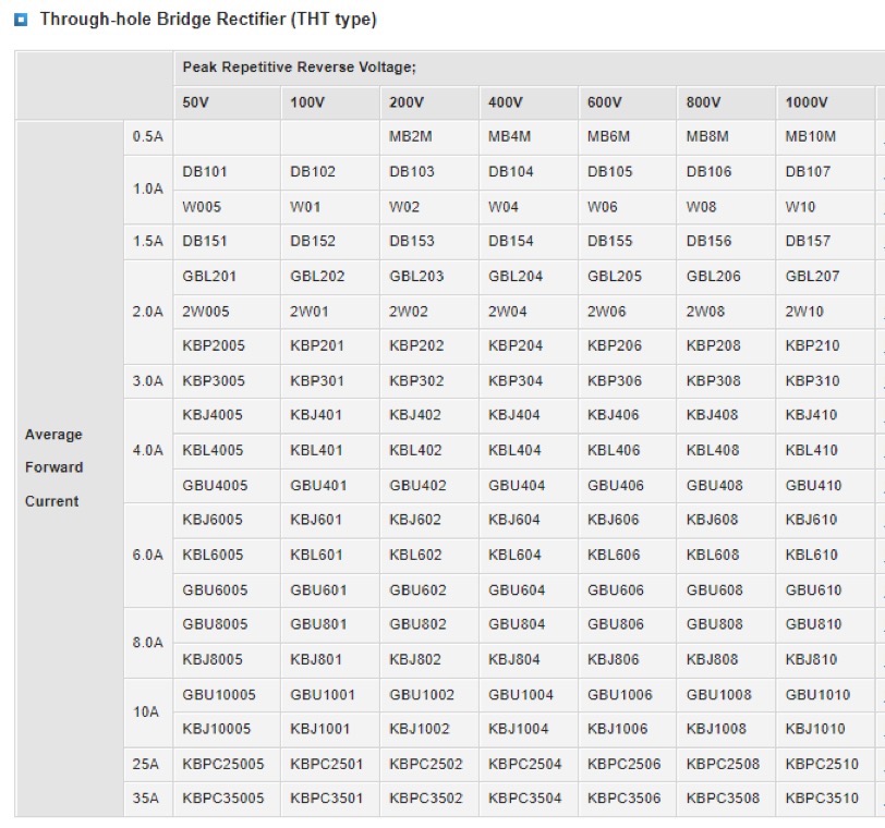
The most common sizes for maximum average rectified current are 1A, 1.5 A, 4 A, 25 A and 35 A. Topdiode has a full selection of bridge rectifier, both through-hole type and SMD bridge rectifier.

For any questions or inquiries, please visit the website:https://www.topdiodes.com/