

What is the difference between an IGBT with Bipolar Transistors
In applications requiring power transistors, the various options such as IGBTs, MOSFETs, and bipolar transistors are used selectively based on an understanding of their strengths and weaknesses. The following is a summary of the features of these different kinds of power transistors.
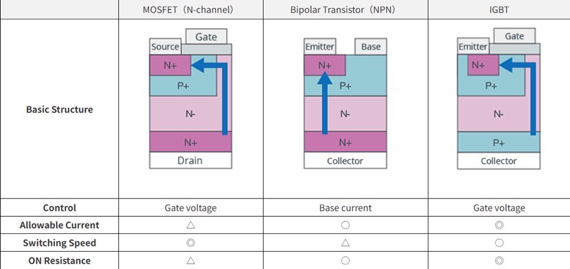
MOSFETs are voltage-driven and have a high input impedance, so that little power is needed to control them; and because they are unipolar transistors, with either electrons or holes as carriers, they also have the advantage of fast switching speeds. However, a conductivity modulation effect such as that in bipolar transistors cannot be used, and so MOSFETs have the drawback of higher on-resistances with higher withstand voltage ratings.
Bipolar Transistors
Bipolar transistors have the advantage of a low on-resistance* even with higher withstand voltage ratings. During operation of a bipolar transistor, both holes and electrons move, and due to the conductivity modulation effect in which the resistance falls due to the entry of holes into the N- layer, the device has a characteristic in which voltage drops are suppressed. Bipolar transistors are current amplifiers, and so a larger current than the applied current can be passed. Drawbacks of these devices include a low input impedance, the large amount of power consumed for device control, and the slow switching speed due to the use of carriers of both polarities.
*The relevant parameter is the saturation voltage.
IGBTs
IGBTs are a hybrid device that combines the structure of a MOSFET in the input section and a bipolar structure in the output section, thereby combining the advantages of MOSFETs and bipolar transistors. The input impedance is high and the device can be driven using minimal power, and amplification to large currents is possible. Moreover, the on-resistance* can be kept low even with higher withstand voltage ratings. Switching speeds are not as fast as those of MOSFETs, but are faster than those of bipolar transistors.
*The relevant parameter is the saturation voltage.
Here are some key differences between IGBTs and MOSFETs:
- Type of Device:
- IGBT:Combines features of both MOSFET and bipolar transistor. It has a voltage-controlled gate like a MOSFET and a bipolar-like current-carrying capability.
- MOSFET:A voltage-controlled transistor that relies on the voltage applied to the gate to control the flow of current between the source and drain terminals.
- Voltage Rating:
- IGBT:Generally suitable for higher voltage applications (hundreds to thousands of volts).
- MOSFET:Typically used in lower to medium voltage applications (tens to hundreds of volts).
- Current Handling:
- IGBT:Well-suited for high current applications. It combines the voltage control of a MOSFET with the current-carrying capability of a bipolar transistor.
- MOSFET:Generally used for lower to moderate current applications.
- Switching Speed:
- IGBT:Slower switching speed compared to MOSFETs. Suitable for applications where switching speed is not the primary concern.
- MOSFET:Faster switching speed, making them suitable for applications that require high-frequency operation.
- Efficiency:
- IGBT:Lower conduction losses compared to a MOSFET at high voltages and currents. Suitable for high-power applications like motor drives and power inverters.
- MOSFET:More efficient at low voltages and currents. Often used in applications where efficiency and fast switching are critical, such as power supplies and certain amplifiers.
- Applications:
- IGBT:Commonly used in high-power applications such as motor drives, power inverters, and induction heating systems.
- MOSFET:Widely used in applications where fast switching and efficiency at lower power levels are crucial, such as voltage regulators and electronic switching circuits.
- Gate Drive Requirements:
- IGBT:Requires a positive voltage on the gate relative to the emitter for turn-on, but the turn-off can be controlled by reducing the gate voltage.
- MOSFET:Requires a positive voltage on the gate relative to the source for both turn-on and turn-off.
The choice between IGBTs and MOSFETs depends on the specific requirements of the application, including voltage and current levels, switching frequency, and efficiency considerations. Each device has its advantages and is better suited to different types of electronic circuits and systems.
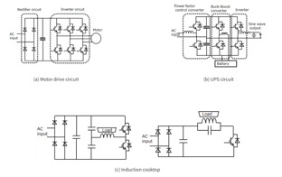
Some application examples for IGBTs.
Because of their high-voltage and high-current characteristics, IGBTs are used as switching devices for motor drive systems, uninterruptible power supplies (UPS), induction cookers, and other applications.
Figure (a) shows an example of a motor drive circuit. IGBTs are widely used as switching devices in the inverter circuit (for DC-to-AC conversion) for driving small to large motors. IGBTs for inverter applications are used in home appliances such as air conditioners and refrigerators, industrial motors, and automotive main motor controllers to improve their efficiency.
Figure (b) shows an example of a UPS circuit. IGBTs are in middle- and large-capacity (several kVA or higher-capacity) models, contributing to high efficiency and space saving.
Figure (c) shows an example of an induction-heating (IH) circuit. Induction heating uses LC resonance for zero-voltage switching (ZVS) or zero-current switching (ZCS) to reduce switching loss. Because of high resonance voltage or resonance current, IGBTs are commonly used. Specifically, IGBT applications include induction cookers, induction rice cookers and microwave ovens.