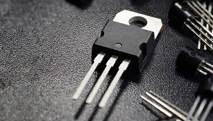


TPGM900HB120MNYA 1200V 900A IGBT Module
Topdiode TPGM900HB120MNYA is a 1200 V, 900 A high-power IGBT module designed for demanding switching applications such as general-purpose inverters, industrial welding, UPS systems and fast electronic current-limiting equipment. The supplied technical data lists a ±20 V gate-emitter rating, 1,800 A pulsed collector current, 8 μs short-circuit capability, a 175 °C maximum junction temperature, low-VCE(sat) trench IGBT technology and an isolated copper baseplate using DBC construction.
| Cross-reference note
The source material identifies TPGM900HB120MNYA as a replacement for GT900HF120T9H. For a production substitution, treat it as a cross-reference candidate until electrical curves, switching losses, thermal resistance, isolation rating, terminal layout, mounting dimensions and gate-drive conditions are confirmed against the original device datasheet. |
TPGM900HB120MNYA Key Specifications
| Parameter | TPGM900HB120MNYA | Engineering significance |
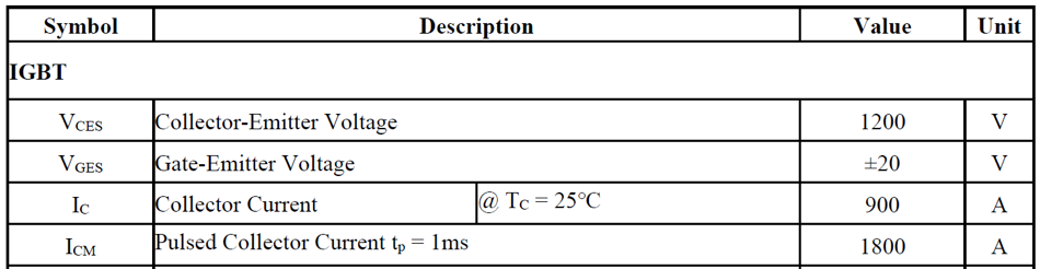
| Collector-emitter voltage (VCES) | 1200 V | Voltage class for high-power industrial DC-link and inverter designs. |
| Gate-emitter voltage (VGES) | ±20 V | Defines the absolute gate voltage limit stated in the supplied ratings. |
| Continuous collector current (IC) | 900 A @ TC = 25 °C | High-current capability for power conversion and protection equipment. |
| Pulsed collector current (ICM) | 1800 A, tp = 1 ms | Short-duration current capability stated in the supplied maximum ratings. |
| Short-circuit capability | 8 μs | Provides a short fault-withstand window for coordinated gate-driver protection. |
| Maximum junction temperature | 175 °C | Supports high-temperature power-module operation when thermal design is adequate. |
| Technology | Low-VCE(sat) trench IGBT | Targets lower conduction loss at high current. |
| Baseplate / insulation | Isolated copper baseplate, DBC | Supports heat spreading and electrical isolation in module assemblies. |
Figure 1 reproduces the maximum-rating table supplied for TPGM900HB120MNYA.
Why a 1200 V / 900 A IGBT Module Is Used in High-Power Systems
An IGBT combines voltage-controlled gate drive with the high-current switching capability required in medium- and high-power converters. At module level, multiple semiconductor chips and freewheeling diodes can be integrated into an electrically insulated package so the designer can manage high current, switching loss and thermal performance in a compact assembly.
- High-power switching: suitable for large currents and high DC-link voltages.
- Low gate-drive power: the insulated gate is voltage controlled.
- Reduced system complexity: module packaging can integrate multiple power chips and diodes.
- Thermal integration: an insulated DBC/copper baseplate provides a practical path to the heatsink.
- Protection coordination: short-circuit ruggedness gives the controller and gate driver time to detect and turn off a fault.
The original draft positions TPGM900HB120MNYA as a replacement for GT900HF120T9H. The supplied comparison data shows the same 1200 V voltage class and a high-current operating range, but a safe replacement decision must go beyond headline voltage and current.
| Item | GT900HF120T9H (supplied source) | TPGM900HB120MNYA (supplied source) |
| VCES | 1200 V | 1200 V |
| VGES | ±20 V | ±20 V |
| Continuous IC | 900 A @ TC = 80 °C; 1450 A @ TC = 25 °C | 900 A @ TC = 25 °C |
| Peak / pulsed current | 1800 A | 1800 A, tp = 1 ms |
| Technology / features | Trench & Field Stop; short-circuit capability; low switching loss; low stray inductance | Low-VCE(sat) trench IGBT; 8 μs short-circuit capability; positive VCE(sat) temperature coefficient |
| Maximum junction temperature | Not stated in the supplied comparison table | 175 °C |
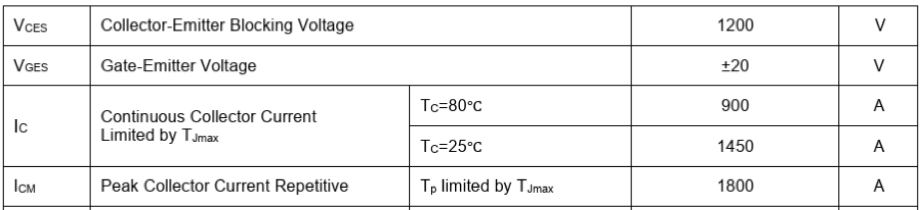
Figure 2. Maximum ratings shown in the source material for GT900HF120T9H.
| Engineer’s replacement checklist
Before approving a drop-in substitution, compare: package outline and mounting holes; terminal positions and polarity; internal circuit topology; VCE(sat) at relevant current and temperature; switching energy (Eon/Eoff); diode recovery data; thermal resistance; isolation voltage; gate-charge / gate-resistance recommendations; short-circuit test conditions; and cooling-interface requirements. |
Applications for TPGM900HB120MNYA
| Application | Why this module class is relevant | Design focus |
| General-purpose inverters | 1200 V / 900 A class supports high-power switching stages. | Switching loss, DC-link voltage margin, heatsink design. |
| Industrial welding | High current and short switching intervals are typical in welding power conversion. | Pulse current, thermal cycling, busbar inductance. |
| UPS systems | High-power inverter stages require robust semiconductor switching. | Efficiency, fault handling, cooling and parallel operation. |
| High-power power supplies | Module construction is suited to high-current conversion. | Conduction loss and thermal impedance. |
| DC/DC and AC/DC modules | Power modules can serve as primary switching devices in high-power converters. | Topology, switching frequency, snubber and gate drive. |
| Electronic fire-prevention current limiters | Fast semiconductor turn-off can actively restrict fault current before a slower mechanical device operates. | Detection speed, short-circuit withstand, energy absorption and fail-safe design. |
How IGBT Modules Work in Electronic Fire-Prevention Current Limiters
In an electronic current-limiting protector, the IGBT module acts as the main high-speed semiconductor switch. When the monitoring circuit detects a short circuit or severe overload, the controller can command the IGBT to turn off or enter a controlled chopping/current-limiting state. This semiconductor action can occur far faster than a purely mechanical trip mechanism, helping reduce the magnitude and duration of fault current.
- Detect the fault. Current or voltage sensing identifies a short circuit or overload condition.
- Issue the gate command. The controller rapidly sends a turn-off or controlled switching command to the IGBT gate driver.
- Limit the fault current. The semiconductor switch interrupts or modulates current before the fault reaches a more damaging level.
- Reduce arcing energy. By shortening the high-current interval, the system can reduce the energy available to sustain an arc.
- Coordinate backup protection. Fuses, breakers and other protection devices should still be designed as part of the complete safety architecture.
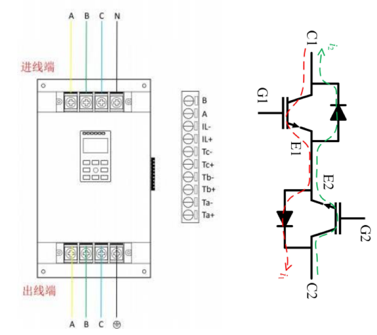
Figure 3. Three-phase electronic fire-prevention current-limiter application diagram from the source document.
| Safety note
A power-semiconductor module alone does not make a fire-prevention device compliant or fail-safe. The complete limiter must be engineered with appropriate sensing, gate-driver protection, insulation, creepage/clearance, thermal design, enclosure, fault-energy coordination and applicable product-safety requirements. |
Topdiode IGBT Module Package Options
The source document also shows a wider Topdiode module portfolio in 34 mm, 62 mm and ED3 package families. These examples help procurement and design teams choose a current class and mechanical platform before detailed electrical validation.
| Package family | Example ratings shown in source | Typical selection consideration |
| 34 mm | 650 V / 150 A, 200 A, 300 A; 750 V / 275 A | Compact power conversion where the required current is below the larger 62 mm/ED3 classes. |
| 62 mm | 650 V / 300 A, 400 A, 600 A; 750 V / 900 A | Higher-current industrial power stages with a larger thermal/mechanical footprint. |
| ED3 | 650 V / 450 A, 600 A; 750 V / 950 A | High-current module platform where the specific circuit topology and terminal layout fit the design. |
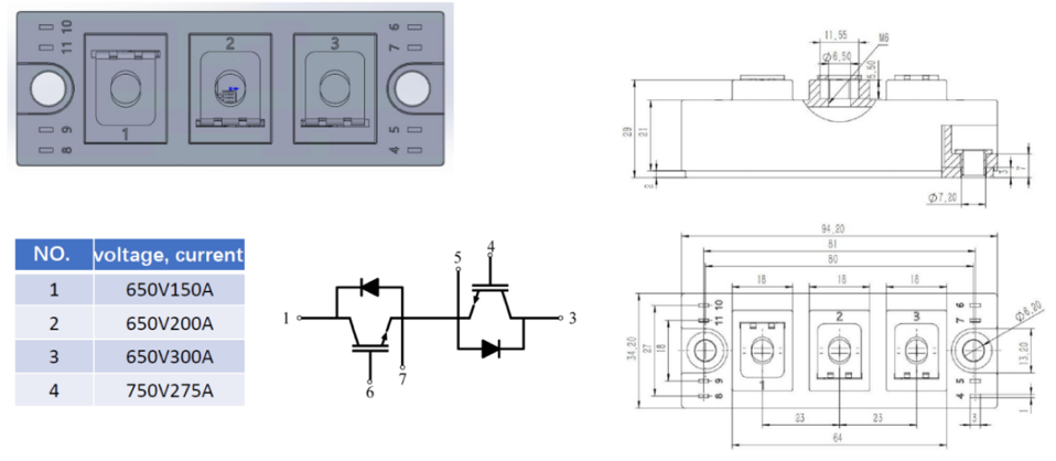
Figure 4. 34 mm package examples and mechanical outline shown in the source document.
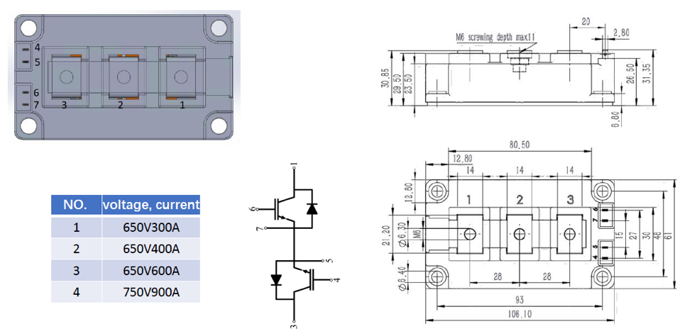
Figure 5. 62 mm package examples and mechanical outline shown in the source document.
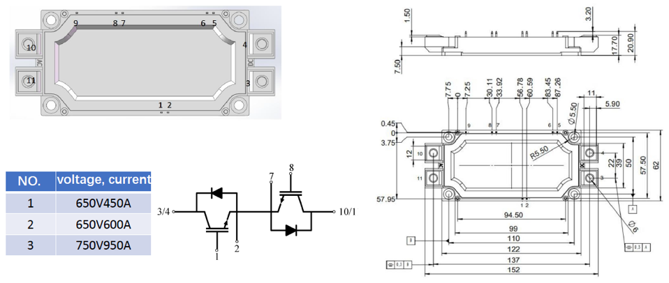
Figure 6. ED3 package examples and mechanical outline shown in the source document.
How to Select a High-Power IGBT Module
For a new design or a cross-reference project, select the module from the system requirements outward rather than by matching only voltage and current labels.
- Voltage margin — Choose VCES with adequate margin above the maximum DC-link voltage and expected overshoot.
- Continuous and pulsed current — Check current at the actual case/junction temperature, not only the room-temperature headline rating.
- Conduction and switching loss — Use VCE(sat), Eon and Eoff at your gate resistance, current and temperature to estimate total semiconductor loss.
- Short-circuit behavior — Coordinate the device short-circuit withstand time with desaturation detection and gate-driver turn-off behavior.
- Thermal path — Confirm junction-to-case thermal resistance, baseplate flatness/interface material, heatsink resistance and coolant/airflow conditions.
- Mechanical compatibility — Verify package outline, terminal spacing, mounting torque, busbar geometry and insulation distances.
- Reliability and qualification — Review RBSOA/SCSOA, thermal cycling, isolation and application-specific qualification requirements.
Why Source High-Power IGBT Modules from Topdiode?
Topdiode positions its semiconductor portfolio around alternative-source support, cost control and shorter project timelines. Its website states that the company supplies IGBTs, MOSFETs, driver ICs and other semiconductors, maintains stock for selected regular items, and supports cross-reference work for customers seeking alternatives to established international brands.
Related internal page: Topdiode IGBT product family | Topdiode News | Topdiode homepage
FAQ
What is the TPGM900HB120MNYA?
TPGM900HB120MNYA is a Topdiode high-power IGBT module rated at 1200 V and 900 A in the supplied maximum-rating table. It uses low-VCE(sat) trench IGBT technology and an isolated DBC copper baseplate.
What is the short-circuit capability of TPGM900HB120MNYA?
The supplied product information specifies an 8 μs short-circuit capability. The gate driver should detect and clear a fault within the conditions allowed by the module datasheet and the complete converter design.
Can TPGM900HB120MNYA replace GT900HF120T9H?
The source document presents TPGM900HB120MNYA as a replacement candidate for GT900HF120T9H. Both are shown in the 1200 V high-current class, but a production substitution should only be approved after electrical, thermal and mechanical parameters are verified against the original datasheet.
Where can a 1200 V 900 A IGBT module be used?
Typical applications include high-power inverters, industrial welding, UPS systems, high-power power supplies, DC/DC or AC/DC converters, and fast current-limiting/protection equipment.
Why is DBC used in IGBT power modules?
Direct-bonded copper (DBC) provides an electrically insulating ceramic layer with copper conductors, allowing the semiconductor chips to be electrically isolated while transferring heat toward the module baseplate and heatsink.
What should be checked before replacing an IGBT module?
Check voltage/current ratings at temperature, VCE(sat), switching energy, diode characteristics, gate conditions, short-circuit behavior, thermal resistance, isolation, circuit topology, package dimensions, terminal layout and mounting requirements.
Summary
TPGM900HB120MNYA targets the 1200 V / 900 A high-power IGBT module class with an 8 μs short-circuit capability, 175 °C maximum junction temperature and isolated DBC copper baseplate. For engineers and buyers evaluating a GT900HF120T9H alternative, the strongest approach is to use the model number as the starting point for a structured cross-reference check—not as the only proof of interchangeability. Once switching, thermal and mechanical compatibility are confirmed, the module can be evaluated for high-power inverter, welding, UPS and electronic current-limiting applications.