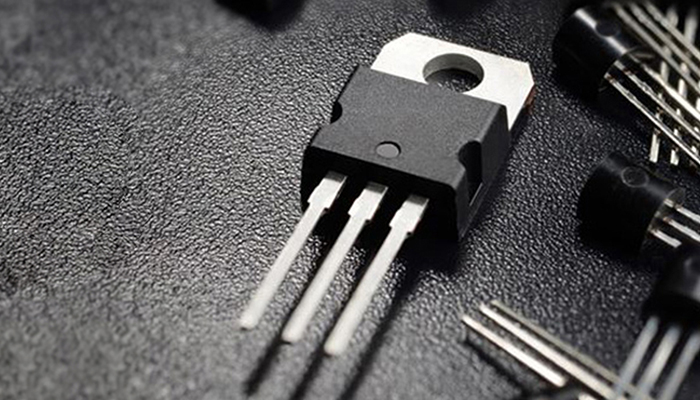


MBR20L60 20A 60V Schottky Rectifier | Low VF & Thermal Guide
The MBR20L60 series is a 20A / 60V low-forward-voltage Schottky rectifier family intended for high-efficiency power conversion where conduction loss matters. The source data covers four package variants—MBR20L60 (TO-220AC), MBR20L60F (ITO-220AC), MBR20L60W (TO-262AC) and MBR20L60D (TO-263 / D2PAK)—with a common-cathode dual-diode configuration. The most important design trade-off is straightforward: lower forward drop reduces conduction loss, but package thermal resistance and reverse leakage determine how much of the nominal 20A rating can actually be used in a hot system.
MBR20L60 Key Ratings at a Glance
| Parameter | Source value | Why it matters |
| Maximum repetitive reverse voltage (VRRM) | 60 V | Sets the repetitive reverse blocking limit. |
| Maximum RMS voltage (VRMS) | 42 V | Relevant when evaluating AC waveform stress. |
| Maximum DC blocking voltage (VDC) | 60 V | Maximum stated continuous DC blocking voltage. |
| Average forward current (IAV) | 20 A | Nominal average forward-current rating in the source data. |
| Peak surge current (IFSM) | 200 A, 8.3 ms half-sine | Important for inrush and fault-energy checks. |
| Operating junction temperature | −55 to +150 °C | Absolute junction-temperature range. |
| Configuration | Dual common cathode | Each electrical value is stated per diode in the source document. |
Why the “Low VF” Rating Matters
In a Schottky rectifier, forward-voltage drop directly translates into conduction loss. The supplied MBR20L60 data gives the following per-diode forward-voltage figures:
- 0.48 V typical / 0.52 V maximum at IF = 15 A, TJ = 25 °C.
- 0.53 V typical / 0.55 V maximum at IF = 20 A, TJ = 25 °C.
- 0.52 V maximum at IF = 20 A, TJ = 125 °C.
- Breakdown voltage VBR ≥ 60 V at IR = 0.5 mA.
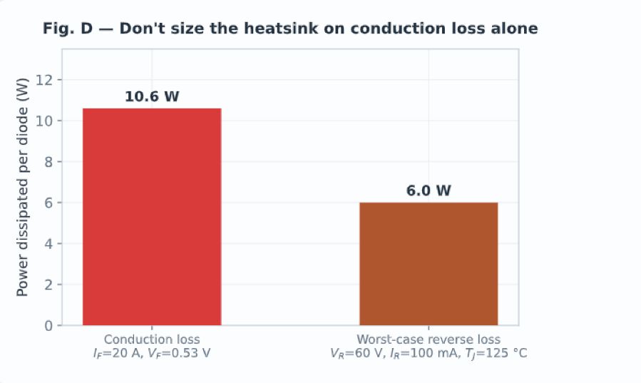
At 20 A and 0.53 V, the simplified conduction-loss estimate is approximately 10.6 W per conducting diode (P ≈ VF × IF). That is why a few hundred millivolts of forward-drop difference can materially change heatsink requirements in a high-current rectifier.
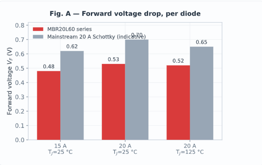
Figure 1. Forward-voltage comparison reproduced from the source article.
Package Selection: Thermal Resistance Changes the Usable Current
The four package versions share the same electrical family concept, but their junction-to-case thermal resistance is not the same. That means package choice can change junction temperature significantly even when current and forward voltage are identical.
| Part | Package | RθJC per diode | Weight |
| MBR20L60 | TO-220AC | 2.0 °C/W | 1.85 g |
| MBR20L60F | ITO-220AC | 4.5 °C/W | 1.70 g |
| MBR20L60W | TO-262AC | 2.5 °C/W | 1.40 g |
| MBR20L60D | TO-263 / D2PAK | 2.5 °C/W | 1.35 g |
The isolated ITO-220AC option has the highest stated RθJC. With the source article’s 10.6 W loss example, the estimated junction-to-case rise is about 47.7 °C for the ITO-220AC package, versus about 21.2 °C for the TO-220AC package. The isolated tab can simplify mechanical insulation, but it comes with a real thermal penalty.
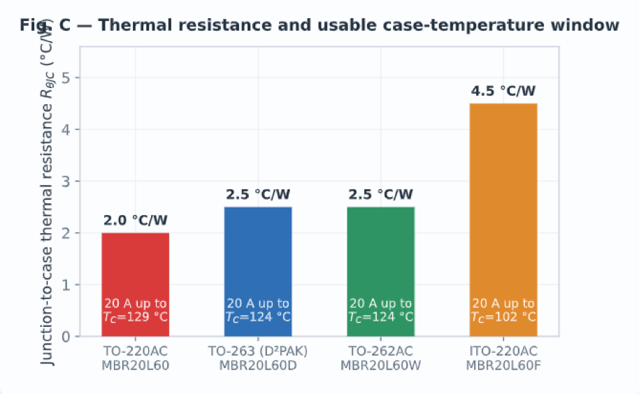
Figure 2. Junction-to-case thermal resistance and modelled usable case-temperature window.
Thermal Derating: When a 20A Rectifier Stops Being a 20A Rectifier
The nominal 20A rating should not be treated as valid at every case temperature. Using the source article’s simplified model with TJ,max = 150 °C and VF = 0.53 V at 20 A, the calculated full-current case-temperature ceilings are:
| Package | RθJC | Power @ 20A | ΔTJ-C | Modelled 20A case-temperature ceiling |
| TO-220AC | 2.0 °C/W | 10.6 W | 21.2 °C | 128.8 °C |
| TO-263 / D2PAK | 2.5 °C/W | 10.6 W | 26.5 °C | 123.5 °C |
| TO-262AC | 2.5 °C/W | 10.6 W | 26.5 °C | 123.5 °C |
| ITO-220AC | 4.5 °C/W | 10.6 W | 47.7 °C | 102.3 °C |
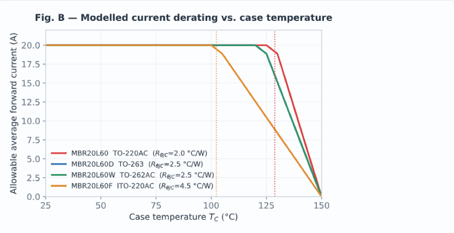
Figure 3. Modelled allowable average current versus case temperature from the source article.
The Reverse-Leakage Trade-Off
Low forward voltage is not free. The supplied data lists reverse current of 150 μA maximum at 25 °C, rising to 100 mA maximum at 125 °C, both at 60 V reverse bias. This matters in OR-ing, reverse-polarity protection and other applications where a diode may remain hot and reverse-biased for long periods.
Using the source article’s worst-case example, 60 V × 100 mA corresponds to 6 W of reverse-side power. That is large enough to influence thermal design and should not be ignored simply because the device is in the blocking state.
Where MBR20L60 Fits Best
The source document positions the MBR20L60 family for applications where a 60V Schottky rectifier can reduce conduction loss while still providing useful surge capability.
| Application | Why MBR20L60 can fit | Main design check |
| SMPS secondary rectification | Low forward drop can reduce rectifier conduction loss. | Reverse-voltage margin, current waveform, heatsink/PCB thermal path. |
| Buck converter freewheeling | Schottky behavior suits low-voltage high-current freewheel paths. | Peak current, duty cycle, junction temperature. |
| Motor-drive freewheel path | Fast Schottky conduction can support low-voltage switching stages. | Surge current and repetitive thermal cycling. |
| Power-rail OR-ing | Low VF reduces series loss in redundant rails. | Reverse leakage at hot blocking conditions. |
| Battery reverse-polarity protection | Low forward loss can reduce voltage drop. | Continuous reverse blocking and thermal budget. |
Choosing Between MBR20L60, MBR20L60F, MBR20L60W and MBR20L60D
| Variant | Package | Best fit | Main trade-off |
| MBR20L60 | TO-220AC | Through-hole designs with heatsink mounting | Lowest stated RθJC in the family. |
| MBR20L60F | ITO-220AC | Designs needing an electrically isolated tab | Highest stated RθJC; derates earlier. |
| MBR20L60W | TO-262AC | Low-profile through-hole / power assembly | Moderate thermal resistance. |
| MBR20L60D | TO-263 / D2PAK | Surface-mount power designs | PCB copper and thermal vias become part of the heatsink strategy. |
Mechanical and Compliance Notes
- Circuit configuration: common cathode; polarity follows the package marking.
- Maximum mounting torque in the supplied source: 5 in-lb.
- Terminals: pure-tin plated and stated as solderable per MIL-STD-202, Method 208.
- Lead-free and stated as compliant with EU RoHS Directive 2011/65/EU.
- Package weights in the supplied source: 1.85 g (TO-220AC), 1.70 g (ITO-220AC), 1.40 g (TO-262AC), 1.35 g (TO-263).
MBR20L60 Design Checklist
- Confirm worst-case reverse voltage remains below 60 V with adequate transient margin. The source document lists VRMS = 42 V.
- Select the package by thermal path, not only by footprint or isolation convenience.
- Calculate both forward conduction loss and reverse-bias loss at the hottest expected operating condition.
- Include thermal-interface and heatsink resistance. The supplied source only gives junction-to-case resistance.
- Check inrush and fault events against the stated 200 A / 8.3 ms surge rating.
- Use a conservative continuous-junction-temperature target rather than designing permanently at the 150 °C absolute maximum.
FAQ
Is MBR20L60 a drop-in replacement for another 20A 60V Schottky rectifier?
Not automatically. A cross-reference should compare package and pinout, VRRM, current-rating definition, VF at the relevant current and temperature, reverse leakage, IFSM, RθJC and the actual thermal environment. Matching 20A and 60V alone is not enough.
Can the two diode legs be paralleled for 40A?
The supplied source advises against assuming reliable 40A operation by simply paralleling both legs. Schottky forward voltage has a negative temperature coefficient, so unequal current sharing can create thermal current hogging unless the design is specifically engineered and validated for parallel operation.
Which MBR20L60 variant is best for surface-mount assembly?
MBR20L60D uses the TO-263 / D2PAK package. The source lists RθJC = 2.5 °C/W. In a surface-mount design, PCB copper area, thermal vias and board temperature become critical parts of the thermal path.
Does the 20A rating require derating?
Yes. The allowable current depends on case temperature and thermal resistance. The source article’s model shows the isolated ITO-220AC variant reaches its full-current thermal ceiling at a much lower case temperature than the TO-220AC version.
Why can a low-VF Schottky have high leakage current?
Schottky barrier design involves a trade-off between forward conduction loss and reverse leakage. Lower forward drop can improve efficiency in conduction, while leakage increases strongly with temperature and must be included in hot reverse-bias thermal calculations.
What are the main applications for a 20A 60V Schottky rectifier?
Typical uses include secondary rectification in switching power supplies, freewheeling paths in low-voltage converters and motor drives, redundant-rail OR-ing, and reverse-polarity protection where the 60V blocking rating is appropriate.
Conclusion
The MBR20L60 family is best understood not simply as a “20A / 60V Schottky,” but as a low-VF rectifier whose usable performance is governed by package thermal resistance and hot reverse leakage. The supplied data highlights four package options, forward drop in the roughly 0.48–0.53 V typical range under the stated conditions, a 200 A surge rating and a 150 °C absolute junction limit. For a reliable design, choose the package by thermal path, derate with case temperature, include reverse-bias loss and keep sufficient voltage margin for the real application.